


Huge growth of data has driven the construction of data center campuses, especially the construction of very large data centers. Now, several buildings in a park must be connected with enough bandwidth. How much bandwidth is needed to maintain the flow of information between data centers in a single campus? Each data center can today transmit to other data centers at up to 200 Tbps, and in the future requires higher bandwidth (see Figure 1).
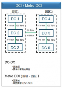
Figure 1. Conceptual campus layout. DCI requirements and distances are unique. Bandwidth requirements can be as high as 100 Tbps or even 200 Tbps.
What is driving such a huge bandwidth demand between campus buildings?
First, the exponential growth of east-west traffic is supported by device-to-device communications. The second trend is related to the adoption of a flatter network architecture, such as a ridge network or a CLOS network. The goal is to have a large network structure in the campus, so a lot of connections need to be made between devices.
Traditionally, data centers have been built on a three-tier topology consisting of core switches, aggregation switches, and access switches. Although mature and widely deployed, the traditional three-tier architecture no longer meets the ever-increasing workload and latency requirements of hyperscale data center campus environments. In response, today’s very large data centers are moving to the spine architecture (see Figure 2). In the spine architecture, the network is divided into two phases. The spin phase is used to aggregate packets and route them to the final destination, and the leaf phase is used to connect the host side to the load balancing connection.
Ideally, each leaf switch will fan out to each spine switch to maximize the connection between servers, so the network requires a high-density spine core switch. In many environments, large spine switches are connected to higher-level spine switches, often referred to as campus or aggregate ion-ridge switches, to connect all the buildings in the campus. Due to this flatter network structure and the use of high-density switches, we expect to see networks become larger, more modular, and more scalable.
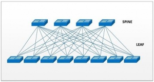
Figure 2. The spine structure and the high-density switch require a large number of interconnects in the data center structure.
How to provide the best connection in the most cost-effective way?
The industry has evaluated a variety of methods, but the prevailing model is to transmit at a lower rate over a large number of fibers. To achieve 200 Tbps using this method, each data center interconnect requires more than 3000 core fibers. When you consider the fiber you need to connect each data center to each data center in a single campus, the density can easily exceed 10,000 core fibers!
A common question is when to use DWDM (Dense Wavelength Division Multiplexing Transceiver) or other technologies to increase the throughput of each fiber instead of increasing the number of fibers? Currently, up to 10 kilometers of data center interconnection Applications typically use a CWDM (Coarse Wavelength Division Multiplexing) 1310nm transceiver that does not match the 1550nm transmission wavelength of the DWDM system. Therefore, high-core fiber optic cables are used between data centers to support large-scale interconnects.
The next question is, when to replace the 1310nm transceiver with a pluggable DWDM transceiver in the access switch by adding a multiplexer unit? The answer is, for the data center interconnect link in the campus, DWDM Whether or not it becomes a cost-effective method.
To estimate the feasibility of this conversion, we need to look at the price of the DWDM transceiver and compare it to the existing transceiver. Based on the price modeling of the entire link, the current forecast is that, for the foreseeable future, connections based on the fiber-rich 1310nm architecture will continue to occupy low cost advantages (see Figure 3). The PSM4 (8-core fiber) alternative has proven to be cost effective for applications less than 2 kilometers, which is another factor in increasing the number of fibers.
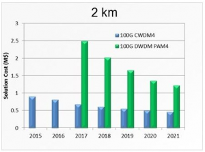
Figure 3. Pluggable DWDM transceiver with 100G CWDM4.
How to choose the right fiber?
Now that we have identified the need for extreme density networks, it is important to understand the best way to build these networks. These networks present new challenges in both wiring and hardware. For example, the use of loose tube cable and single core fiber fusion is not scalable or feasible. If a loose tube design is used to install a 1728 core fiber, assuming a joint of 4 minutes, the weld time will exceed 100 hours. If a ribbon cable configuration is used, the welding time will be reduced to less than 20 hours. Although 20 hours still requires a lot of time for welding, it saves a lot of time compared to the single-core cable type.
At the same time, traditional fiber optic cable designs are also facing significant challenges when installed in commonly used 2 or 4 inch pipes. New fiber optic cable and ribbon designs have entered the market, and fiber capacity has roughly doubled in the same cross-sectional area. These products are usually divided into two design methods: one using a standard matrix strip with tighter packageable subunits and the other using a standard cable design with a center or slot core design with loosely overlapping layers that overlap each other. Network design band (see Figure 4).
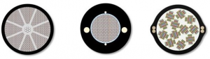
Figure 4. Different ribbon cable designs for extreme density applications.
With these new fiber optic cable designs, higher fiber densities can be achieved in the same pipe space. Figure 5 illustrates how different fiber optic cable combinations of different extreme density types can be used to enable network owners to achieve the fiber density required for very large grade data center interconnects.
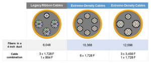
Figure 5. Designed with an extremely dense fiber optic cable that doubles the fiber capacity of the same pipe space.
When leveraging these new ribbon cable designs, network owners need to consider hardware and connectivity options that can handle and scale these very high fiber counts. It can easily overwhelm existing hardware, and there are several key areas to consider when building a complete network.
How many building internal cables do you need to install to connect to 1728 to 3456 fiber optic building external cables? If you currently use 288 fiber ribbon cables in an internal building environment, your hardware must be able to accommodate 12 to 14 cables. Your hardware must also manage 288 separate ribbon welds. It is not feasible or desirable to use any single-core cable and single-core fiber fusion method in this application because of the long preparation time and difficulty in fiber management.
Another area that can be challenging is tracking fiber to ensure proper fusion. Due to the large number of fibers that must be tracked and routed, the fiber needs to be fully labeled and categorized immediately after the cable is opened. To avoid damaging any fiber, priority should be given to bundling and protecting the ribbon stack when loaded into the hardware. In most installations, errors that cause the cable to be re-prepared are controllable. In the case of an extremely dense network, an error can have a serious impact on the completion of the project and may only be delayed by one week due to one point.
How will the future of extreme density networks develop?
The most important factor at the moment is whether the number of fibers will stop at the 3456 core, or if we see these numbers will be higher. Current market trends indicate that the number of cores requires even more than 5000 cores. In order to keep the infrastructure still large, the pressure to reduce the size of the cable will increase. As fiber packing densities are approaching their physical limits, the option to further reduce cable diameter in a meaningful manner becomes more challenging.
An increasingly popular method is to use an optical fiber whose coating size is reduced from the usual 250 um to 200 um. The core and cladding dimensions remain the same, so there is no change in optical performance. However, this reduction in size can greatly reduce the overall cross-sectional area of the cable when extended to hundreds to thousands of core fibers in the cable. This technology has been used in some fiber optic cable designs and is used by manufacturers for miniature loose tube cable.
Another important issue is how to best provide data center interconnects to connect locations that are much farther apart and not configured in the same physical campus. In a typical data center campus environment, typical data center interconnects are no more than 2 kilometers in length. These relatively short distances enable a cable to provide a connection without any splices. However, as data centers are deployed around large cities to reduce latency, distances are increasing and can approach 75 kilometers. The use of extreme density cable designs in these applications reduces the budget because the cost of connecting a large number of fibers over long distances is high. In these cases, more traditional DWDM systems will continue to be the preferred choice, running at 40G and higher using less fiber.
We can expect that the demand for extreme density cables will migrate from the data center environment to the access market as network owners prepare for the upcoming launch of fiber-intensive 5G products. Developing products that can be effectively scaled to achieve the required number of fibers will continue to be an industry challenge without damaging existing pipelines and the internal environment of the building.
