


The data center has become the engine of modern life, and the growing network information is transmitted and stored at high speed through the data center. Most of the data center’s internal connection distance is short, ranging from a few meters to a few hundred meters. In these short-distance high-speed data communications, multimode fibers and optical modules with vertical cavity surface emitting lasers (VCSELs) as the core components are widely used. Compared with the single-mode transmission scheme, the multi-mode scheme uses a low-cost, low-power laser to achieve fast and efficient coupling between the fiber and the laser. Multimode fiber can achieve higher transmission rates or longer transmission distances than copper cables, and lower cost than single mode fiber systems. At present, the data center internal connection rate has reached 100 Gbit/s, and 400 Gbit/s is also just around the corner. The industry has been developing new multimode fibers to improve its performance, including broadband multimode fiber technology for wavelength division multiplexing in a single fiber; longwave multimode fiber for longer transmission distances. In addition, in order to support high-density, miniaturized connections, improve data center space utilization, heat dissipation efficiency and cable management efficiency, multimode fiber with bending performance has also been rapidly developed and deployed. This paper will combine the technical principles of multimode fiber and the evolution of optical module technology to discuss the development trend of multimode fiber supporting high rate optical modules.
1. Multimode fiber technology and application scenarios
The development of cloud computing has promoted the development of very large data centers, resulting in a different development trend from traditional enterprise data centers. Whether domestic or international, cloud computing business-based hyperscale data center users have evolved significantly faster than server-wide data centers. Traditional enterprises will use multimode OM4 fiber stably, and more than 90% of the system link length is less than 100m.
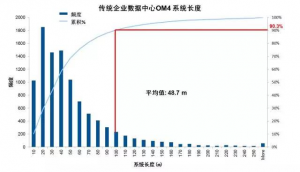
Figure 1. Length distribution of the traditional enterprise data center OM4 system
Ultra-large-scale data center users are more likely to choose single-mode fiber, and 70% of the system link length exceeds 100m.
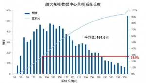
Figure 2. Single-mode system length distribution in a very large data center
The development of very large data centers has increased the use of single-mode fiber, but multimode fiber still has its unique advantages. These advantages include the ability to use lower cost optical modules, lower power consumption, and the transmission distance covering most of the links in the data center, so solutions based on multimode fiber and multimode optical modules still have very attractive customers.
- Bandwidth of 850 nm multimode fiber
Unlike single-mode systems, the transmission distance and rate of multimode systems are limited by the bandwidth of multimode fibers. To support higher speed systems to transmit longer distances, it is necessary to increase the mode bandwidth of multimode fibers. Multimode fiber designs typically use a graded index a profile to reduce mode group delay and achieve high bandwidth:

Where r0 is the core radius and r0 is the maximum value of the relative refractive index change of the core, which can be expressed as follows:
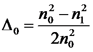
Where n0 is the central refractive index of the core and n1 is the refractive index of the cladding.
By choosing the appropriate value of a, the mode bandwidth of the multimode fiber can be optimized over a range of wavelengths. Figure 3 shows the bandwidth distribution of a 50 μm multimode fiber with a value of 1% change at a wavelength of 850 nm. When the a value of the fiber is at the optimum position, the bandwidth value exceeds 13 GHz.km. The figure also reflects that the bandwidth of the multimode fiber is very sensitive to the value of a. For maximum bandwidth, very fine control of the a value (core refractive index) is required, otherwise the core profile is defective in the manufacturing process which will affect the actual bandwidth of multimode fiber.
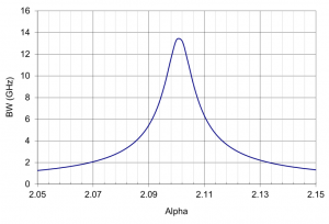
Figure 3 Bandwidth distribution of a 50 μm multimode fiber with a value of 1% change at 850 nm
With advances in fiber design and manufacturing processes, the bandwidth of multimode fiber has increased dramatically. Table 1 shows different types of standard multimode fibers. The 62.5 μm multimode fiber has a high numerical aperture and a large core. It can couple LED light sources (LEDs) into the fiber and support 10 Mbit/s or even 100 Mbit. With the development of Ethernet standards and low-cost 850 nm VCSELs, multimode fiber with 50 μm core fiber is more popular. The fiber has lower modal dispersion and higher bandwidth, and the VCSEL has a smaller spot size and numerical aperture than the LED, making it easy to couple the laser into a 50 μm fiber. By optimizing the fiber manufacturing process and using advanced refractive index control technology, 50 μm multimode fiber has evolved from OM2 (500 MHz.km) to OM3 (2 000 MHz.km) and has now evolved to OM4 (4 700 MHz.km).
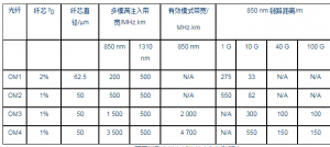
For multimode systems using 850 nm VCSELs, further increasing the bandwidth of the OM4 multimode fiber does not allow the optical module to travel longer distances because the system bandwidth depends on the effective mode bandwidth and dispersion of the fiber (with the spectral linewidth of the VCSEL laser and the combined role of fiber wavelength correlation). If you need to increase the system bandwidth, in addition to the effective mode bandwidth of the fiber, you need to optimize the dispersion value. This can be compensated by differential mode delay (DMD) multimode fiber compensation for partial dispersion, or a narrower linewidth 850 nm VCSEL or a longer dispersion region with lower dispersion.
The maximum relative refractive index of the core, 0, also has an effect on the maximum bandwidth. Since the bandwidth is proportional to 1/2, as shown in Figure 4, when the core 0 is reduced from 1% to 0.75%, the bandwidth will be doubled. However, lowering the core 0 will increase the bending loss, and it is necessary to improve the bending performance by optimizing the fiber structure design.
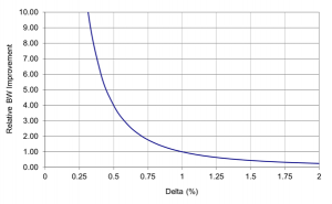
Figure 4: Multi-mode fiber bandwidth versus core relative refractive index
- Bending insensitive multimode fiber
In data center applications, bend-insensitive multimode fiber is used more and more widely, it can optimize the design of fiber optic cable, hardware and equipment to save more space, have better cooling efficiency and more convenient connections and cables management. Figure 5 shows the refractive index profile of a bend-insensitive multimode fiber. The core is a graded index and the cladding has a low index trench. The trench reduces the optical power in the cladding and prevents leakage of the optical signal, thereby improving the bending performance of the optical fiber. The fiber design optimizes the core and trench dimensions to balance bending performance with compatibility with standard multimode fiber. Multimode fiber can achieve high bandwidth and low bending loss at the OM4 level by properly designing the core and trench. Figure 6 shows the bending loss measured at 850 nm. The macrobend loss of the bend-insensitive multimode fiber is 10 times lower than that of the conventional standard multimode fiber.
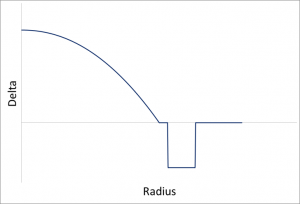
Figure 5 Refractive index profile of a bend-insensitive multimode fiber
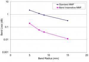
Figure 6 Comparison of bending loss for standard and bend insensitive multimode fibers
- Development of next-generation multimode fiber
At present, the highest mode bandwidth of 850 nm multimode fiber is OM4 fiber, which can support 100 meters transmission of 100G system. If the mode bandwidth is further increased, a finer control of the refractive index distribution is required, which puts higher requirements on the production process and has a greater impact on the yield of the product. On the other hand, the total bandwidth of the system is limited by the two factors of fiber mode bandwidth and fiber dispersion. The single mode-enhanced bandwidth has limited improvement on system transmission performance. This is because multimode fiber dispersion is the most important limiting factor affecting rate and link distance due to the linewidth of the currently used VCSEL. If you want to increase the system transfer rate or transmission distance, you can usually use two methods: use single mode fiber and single mode laser; or still use multimode fiber, but use a narrower linewidth laser to limit the incident mode of multimode fiber. The disadvantage of these two approaches is that more expensive lasers are required, and the fiber coupling process requires higher alignment accuracy, which leads to higher and optical module cost and connection costs. There is therefore a need to improve multimode fiber technology to achieve higher capacity and longer range transmission. The research on new multimode fiber is mainly focused on the following directions.
4.1 Long wave multimode fiber
Long-wave optimized high-bandwidth multimode fiber (980 nm / 1 060 nm or 1 310 nm) combined with a light source (such as long-wave VCSEL) is a viable solution for long-haul, high-rate transmission. The long-wave multimode fiber system retains the advantages of low coupling loss and easy alignment of conventional 850 nm multimode fiber, while the fiber has lower dispersion and attenuation values. As shown in Figure 7, the dispersion and loss of the fiber vary with wavelength. The dispersion and loss are reduced by half at 850 nm at 1060 nm, the dispersion is almost zero at 1310 nm, and the loss is only 20% at 850 nm. A low-loss, low-dispersion multimode fiber system operating in the long-wave region enables higher speeds and longer transmission distances. A series of experimental results in recent years have also confirmed this conclusion: 1310 nm multimode fiber combined with 1310. The nm optical module achieves a transmission distance of over 820 m. The combination of 1060 nm multimode fiber and 1060 nm VCSEL laser enables transmission over 500 m (all experiments are 100 G rate).
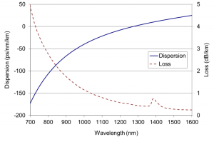
Figure 7 Dispersion and loss of multimode fiber
4.2 Broadband Multimode Fiber
Based on the 40G/100G standard developed by IEEE802.3ba, the transmission of multimode fiber 40G adopts a rate of 10 Gbps per pair of optical fibers 4*10 Gbp=40 Gbps, which requires 4 fibers to be transmitted and received, a total of 8 core fibers, and 100G each. 4 optical fibers are transmitted and received 4*25Gbps=100G, and a total of 8 core fibers are used. The 400 Gb/s transmission rate requires 16 pairs of 32-core fibers, which is very large for fiber resources. The industry is exploring ways to reduce the amount of fiber used by using multiple wavelength multiplexing.
There are currently two products based on multi-wavelength multiplexing technology on the market. One is the BiDi (Bi-direction) technology. As shown in the following figure (for example, 40G), the optical module has two 20 Gbps bidirectional channels, each of which has transmit and receive functions (multimode fiber supports 850 nm and 900 nm). Two wavelengths), 40G transmission is finally achieved on 2 fibers, and no additional MPT connectors are required. It is worth noting that the port branching function is not supported because each fiber of the BiDi transceiver transmits and receives signals. Another technique is short wavelength division multiplexing (SWDM) technology. Similar to BiDi, SWDM requires only a two-core LC duplex connection, except that SWDM needs to operate at four different wavelengths between 850 nm and 940 nm, one for transmitting signals and the other for receiving signals.
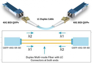
Figure 8 40GBiDi optical module and optical path diagram
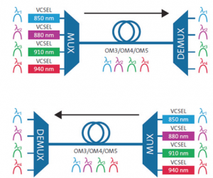
Figure 9. SWDM module light path diagram
Conventional OM3/OM4 fiber bandwidth is typically optimized for 850 nm only. To support the operating mode of SWDM optical modules, the fiber performance at 940 nm needs to be quantified. The Telecommunications Industry Association (TIA) therefore created a working group in 2014 to develop a “WB MMF” related guide to support SWDM transmissions, and the WB MMF’s TIA-492AAAE standard was released in June 2016. Broadband multimode fiber is actually an extended-performance OM4 fiber because broadband multimode fiber must still meet the bandwidth requirements of OM4 fiber at EMB ≥ 4700 MHz?km at 850 nm, and also specify EMB at 953 nm Meet ≥ 2470 MHz?km. In October 2016, the International Standards Organization named broadband multimode fiber as OM5 fiber.
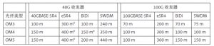
Table 2: Transmission distances for different fiber types and transceiver types (meters)
Note 1: Distance represents the parameters published by the transceiver manufacturer; some switch vendors offer different parameters.
Note 2: Projects with * can achieve longer transmission distances, using some of the connectivity solutions available on the market.
Table 3 compares the transmission distances of different optical modules (OM3/4/5) for matching different optical modules. BiDi and SWDM using OM4 fiber can transmit 150m and 350m respectively in 40G, and OM5 in 100G module can support 150m transmission of BiDi and SWDM optical modules. In contrast, OM3 and OM4 have transmission distances of 70m and 100m, but This distance is sufficient for most multi-mode scenarios. Figure 10 shows the optical module solution based on OM4 fiber at various speeds of 100 meters. OM4 can support multiple optical module solutions from 40G to 400G (such as 100G SR4, 100GBiDi, 400GSR4.2, 400GSR8, etc.) . In practical applications, you should select the appropriate multimode fiber in combination with the application scenario. For example, in the scenario where the SR4/eSR4 optical module needs to be used for port branching, the performance of OM5 and OM4 is basically the same, so OM4 is a more cost-effective solution. With a transmission distance of more than 100 m at a rate of 100G or more, the OM5 / SWDM combination can reflect the advantages of long-distance transmission.
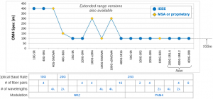
Figure 10 40/100G/400G solution based on OM4 transmission 100m
